
Programmable Logic Controllers (PLCs) are vital for industrial automation, offering reliable control through logic-based decisions, as detailed in numerous online PDF resources;
What is a Programmable Logic Controller?
Programmable Logic Controllers (PLCs) represent a robust, solid-state computing solution specifically designed for industrial environments. These devices continuously monitor input signals – derived from sensors and switches – and, based on a pre-programmed set of instructions, control output devices like motors, valves, and solenoids. Essentially, a PLC automates processes that were traditionally managed by relays, timers, and counters.
Numerous PDF documents detail how PLCs execute logic, making decisions, and controlling machinery. They are fundamentally digital computers optimized for real-world input/output (I/O) operations. Understanding their core function, as explained in available PDF manuals, is crucial for anyone involved in industrial automation and control systems. They offer flexibility and reliability beyond traditional hard-wired control systems.
Historical Development of PLCs
The genesis of Programmable Logic Controllers (PLCs) lies in the automotive industry of the late 1960s, specifically General Motors’ need to replace complex relay logic systems with a more flexible and reliable solution. Early PLCs, documented in historical PDF reports, were large and expensive, but quickly evolved due to advancements in microprocessing technology.
PDF resources illustrate how the 1970s saw a rapid decrease in PLC size and cost, alongside an increase in functionality. This led to widespread adoption across various industries. Subsequent decades brought improvements in processing speed, memory capacity, and communication capabilities. Detailed timelines, often found in manufacturer PDF guides, showcase this evolution, highlighting the shift from proprietary systems to open standards.

PLC Hardware Components
PLC systems comprise a CPU, power supply, and I/O modules; detailed component breakdowns are readily available in comprehensive hardware PDF manuals.
CPU (Central Processing Unit)
The CPU is the brain of the PLC, responsible for executing the control program. It fetches instructions from memory, processes inputs, and updates outputs accordingly. Modern PLC CPUs utilize microprocessors for rapid calculations and decision-making.
PDF documentation often details CPU specifications like processing speed, memory capacity, and supported programming languages. Understanding these parameters is crucial for selecting a CPU suitable for the application’s complexity. Different CPU models offer varying levels of performance and features, impacting the overall system’s capabilities. Detailed PDF manuals provide insights into the CPU’s architecture and instruction set, aiding in efficient program development and troubleshooting. They also outline compatibility with specific I/O modules and communication protocols.
Power Supply
The power supply provides the necessary voltage and current to operate the PLC and its associated modules. It converts standard AC power into the DC voltages required by the internal components. Reliable power is essential for consistent and safe operation of the control system.
PDF datasheets for PLCs meticulously specify power supply requirements, including voltage ranges, current draw, and protection features. These documents detail input voltage compatibility (e.g., 120VAC, 240VAC) and output voltage levels (e.g., 5VDC, 24VDC). Understanding these specifications is vital for proper installation and preventing damage. PDF manuals also outline safety precautions related to power supply connections and grounding, ensuring a secure and stable operating environment for the entire automation system.
Input/Output (I/O) Modules
Input/Output (I/O) modules form the interface between the PLC and the external world, enabling it to monitor and control processes. These modules convert real-world signals – from sensors and switches – into a format the PLC can understand, and vice versa, controlling actuators and devices.
PLC PDF documentation extensively details I/O module specifications, including voltage levels, current ratings, and wiring configurations. Datasheets categorize modules as discrete (on/off signals) or analog (continuous signals). PDF manuals provide wiring diagrams illustrating proper connections for various sensor types and actuators. They also outline troubleshooting steps for common I/O issues, ensuring reliable data acquisition and control. Proper understanding of these PDF resources is crucial for successful system integration.
Discrete I/O Modules
Discrete I/O modules handle on/off signals, representing binary states like switch positions or relay coil activation. PLC PDF manuals thoroughly explain these modules, detailing input characteristics like voltage range and impedance, and output specifications such as current sinking or sourcing capabilities.
Wiring diagrams within these PDF resources illustrate connecting various discrete devices – pushbuttons, limit switches, solenoids – to the module. They specify proper wiring techniques, including common configurations and safety precautions. Troubleshooting guides within the PDF documentation address common issues like false triggering or output failures. Understanding these PDF details is essential for reliable discrete signal handling in automated systems, ensuring accurate process control and safety.
Analog I/O Modules
Analog I/O modules process continuous signals, like temperature, pressure, or flow rate, converting them into digital values for the PLC. Comprehensive PDF documentation details resolution (number of bits), input ranges (0-10V, 4-20mA), and accuracy specifications. These PDF resources often include calibration procedures to ensure precise measurements.
Wiring diagrams within the PLC manufacturer’s PDF guides illustrate proper connections for sensors and actuators. They specify grounding requirements and shielding techniques to minimize noise interference. Troubleshooting sections in the PDFs address common issues like signal drift or offset errors. Mastering the information in these PDFs is crucial for accurate analog signal processing, enabling sophisticated control strategies in industrial applications.

PLC Programming Languages
PLC programming utilizes languages like Ladder Diagram and Structured Text, detailed in PDF manuals, enabling control logic creation and modification for automated systems.
Ladder Diagram (LD)
Ladder Diagram (LD) is a graphical PLC programming language resembling electrical relay logic schematics. Widely used due to its intuitive nature, especially for electricians familiar with relay control systems, LD represents logic as energized “rungs” with input and output conditions. Numerous PDF tutorials and manuals detail LD’s symbols – contacts (inputs) and coils (outputs) – connected by lines representing power flow.
Complex logic is built by combining these elements with timers, counters, and other functions. Learning resources, often available as downloadable PDF guides, demonstrate how to create interlocking circuits, sequential operations, and data manipulation using LD. Mastering LD is crucial for troubleshooting and modifying existing PLC programs, as it remains a dominant language in many industrial applications. Comprehensive PDF documentation aids in understanding its nuances.

Function Block Diagram (FBD)
Function Block Diagram (FBD) is a graphical PLC programming language utilizing pre-defined function blocks to represent specific operations. These blocks, with inputs and outputs, are interconnected to create complex control systems. Many introductory PDF guides illustrate FBD’s modular approach, simplifying program development and maintenance. Unlike Ladder Diagram, FBD focuses on data flow rather than relay logic.
Common function blocks include timers, counters, PID controllers, and mathematical functions. Detailed PDF documentation explains each block’s functionality and parameters. FBD excels in process control applications where continuous data manipulation is essential. Learning resources, often available as free PDF downloads, demonstrate building sophisticated control strategies. Understanding FBD, through available PDF materials, is key for advanced PLC programming.
Structured Text (ST)
Structured Text (ST) is a high-level, text-based PLC programming language resembling Pascal. It’s ideal for complex algorithms and mathematical operations, offering greater flexibility than graphical methods. Numerous PDF tutorials detail ST’s syntax and capabilities, emphasizing its power for advanced control tasks. Unlike Ladder Diagram, ST uses statements, loops, and conditional logic for program execution.
PDF resources often showcase ST’s use in data manipulation, calculations, and complex sequencing. Mastering ST, through dedicated PDF study materials, unlocks advanced PLC programming potential. It’s particularly useful for applications requiring precise control and intricate logic. Comprehensive PDF documentation explains ST’s operators, data types, and programming structures, enabling efficient and robust PLC applications.
Instruction List (IL)
Instruction List (IL), also known as assembly language, is a low-level PLC programming language. It utilizes mnemonics to represent machine instructions, offering direct control over the processor. Many PDF guides explain IL’s syntax, which can be challenging for beginners but provides maximum control. It’s often used for optimizing performance or accessing specific hardware features.
PDF documentation frequently demonstrates IL’s use in bit manipulation and precise timing control. While less intuitive than graphical languages, IL, as detailed in PDF resources, allows for highly efficient code. Learning IL, through dedicated PDF study, is beneficial for experienced PLC programmers. Comprehensive PDFs cover IL’s instruction set, addressing modes, and programming techniques for advanced applications.
Sequential Function Chart (SFC)
Sequential Function Chart (SFC) is a graphical PLC programming language ideal for representing sequential processes. It organizes control logic into steps and transitions, making complex systems easier to understand. Numerous PDF tutorials illustrate SFC’s structure, utilizing steps (actions) and transitions (conditions). These PDF resources highlight its suitability for batch processes and state machines.
PDF documentation often showcases SFC’s ability to manage complex sequences with clear visual representation. Learning SFC, aided by detailed PDF guides, simplifies troubleshooting and maintenance. Advanced PDFs cover nested SFCs and parallel execution. Mastering SFC, through dedicated PDF study, is crucial for designing robust and maintainable PLC applications, as demonstrated in various industrial PDF case studies.

PLC Software and Programming Environments
PLC software, often detailed in PDF manuals, provides tools for programming, simulation, and debugging, crucial for effective controller management and automation.
Programming Software Overview
PLC programming software serves as the primary interface for developing and deploying control logic. These integrated development environments (IDEs), frequently available as downloadable PDF guides from manufacturers, support various programming languages like Ladder Diagram, Function Block Diagram, and Structured Text.
Key features commonly include a project management system for organizing code, a code editor with syntax highlighting, and compilation tools to translate the program into machine-executable code. Many software packages also offer built-in simulation capabilities, allowing engineers to test their logic virtually before deploying it to a physical controller.
Furthermore, advanced software often incorporates features like version control, collaborative editing, and online monitoring, enhancing productivity and simplifying troubleshooting. Accessing comprehensive PDF documentation is essential for mastering these tools.
Simulation and Debugging Tools
PLC simulation and debugging tools are crucial for verifying program functionality before deployment, often detailed in manufacturer-provided PDF manuals. Simulation allows engineers to virtually test code, identifying potential errors and optimizing performance without risking damage to hardware. These tools emulate the PLC’s environment, including inputs, outputs, and internal registers.
Debugging features typically include breakpoints, single-stepping, and variable monitoring, enabling precise analysis of program execution. Online monitoring capabilities allow real-time observation of PLC operation, facilitating troubleshooting during live processes. Comprehensive PDF documentation explains how to effectively utilize these features.
Advanced tools may offer trend analysis and data logging, providing valuable insights into system behavior and aiding in root cause analysis.

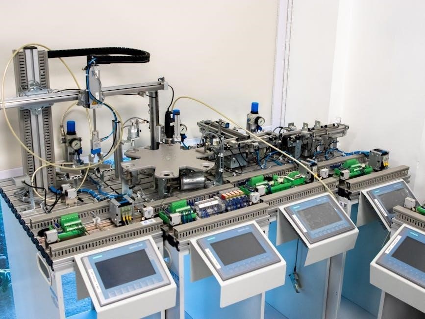
PLC Applications in Industrial Automation
PLCs excel in automating manufacturing, process control, and robotics, with detailed application examples often found within comprehensive PDF guides and documentation.
Manufacturing Processes
PLCs are fundamentally integrated into modern manufacturing, orchestrating complex sequences like assembly line control, packaging systems, and material handling. Detailed PDF manuals from manufacturers showcase how PLCs manage these processes, optimizing efficiency and reducing downtime. These documents often include example programs and wiring diagrams specifically tailored for manufacturing applications.
Furthermore, PDF resources illustrate PLC implementation in quality control systems, utilizing sensors and logic to identify and reject defective products. The ability to precisely control machinery and respond to real-time data makes PLCs indispensable. Studying these PDF guides reveals how PLCs contribute to increased production rates and improved product consistency within diverse manufacturing environments.
Process Control Systems
PLCs excel in process control, managing continuous operations like chemical processing, water treatment, and oil refining. Comprehensive PDF documentation details how PLCs monitor variables – temperature, pressure, flow rate – and adjust control elements accordingly. These PDF resources often feature PID loop configurations and advanced control strategies implemented within the PLC environment.
Manufacturers’ PDF manuals demonstrate PLC applications in maintaining stable process parameters, ensuring product quality and safety. They illustrate how PLCs integrate with SCADA systems for remote monitoring and control. Studying these guides reveals the PLC’s role in optimizing resource utilization and responding to process disturbances, crucial for efficient and reliable operation.
Robotics and Machine Control
PLCs are fundamental to modern robotics and machine control, orchestrating complex movements and sequences. Detailed PDF guides from automation vendors showcase PLC integration with robotic arms, conveyor systems, and specialized machinery. These PDF resources often include sample code and wiring diagrams for common robotic applications.
PLC programming, as explained in numerous PDF tutorials, enables precise control of motor speeds, positioning, and safety interlocks. Manufacturers’ PDF manuals demonstrate how PLCs handle communication protocols like Ethernet/IP and PROFINET, essential for coordinating multiple robotic cells. Studying these documents reveals how PLCs enhance machine performance, reliability, and overall automation efficiency.

PLC PDF Resources and Documentation
PLC manuals and datasheets, readily available as PDF downloads, are crucial for understanding system specifications, wiring, programming, and troubleshooting procedures.
Finding PLC Manuals Online
Locating PLC manuals online is often the first step in understanding and maintaining these critical industrial controllers. Manufacturers like Siemens, Allen-Bradley (Rockwell Automation), and Schneider Electric typically host extensive libraries of PDF documentation on their official websites. These resources include user manuals, programming guides, hardware specifications, and troubleshooting documentation.
Furthermore, dedicated online repositories and forums specializing in industrial automation frequently archive older or hard-to-find manuals. Websites offering searchable PDF databases can be invaluable. Google searches using specific PLC model numbers combined with “manual” or “datasheet” consistently yield relevant results. Always verify the source’s credibility to ensure the PDF is authentic and up-to-date, preventing potential operational issues.
Understanding PLC Datasheets
PLC datasheets, often available as PDF documents, are crucial for selecting and integrating programmable controllers. These documents detail critical specifications like input/output (I/O) capacity, power requirements, memory size, and communication protocols. Understanding these parameters ensures compatibility with existing systems and future expansion needs.
Datasheets also outline environmental operating conditions – temperature ranges, humidity tolerance, and vibration resistance – vital for reliable operation in industrial settings. Pay close attention to the electrical characteristics, including voltage and current limits, to prevent damage. Thoroughly reviewing the PDF datasheet before purchase or implementation minimizes risks and optimizes performance.
Interpreting PLC Wiring Diagrams (PDF)
PLC wiring diagrams, commonly found as PDF files, are essential for correct installation and troubleshooting. These diagrams illustrate the connections between the PLC, input devices (sensors, switches), and output devices (motors, valves). Understanding the symbols used – typically standardized – is paramount. Pay attention to wire numbers, terminal designations, and power supply connections.
PDF diagrams often include details about field wiring, addressing schemes, and grounding requirements. Carefully examine the diagram to identify the correct wiring sequence and avoid potential short circuits or damage. Proper interpretation ensures safe and reliable operation of the automated system, reducing downtime and maintenance costs.